Open-source hardware
Tholus Flow
Open-source sensor for people counting and proximity detection based on ESP32 + VL53L8CH. This page brings together hardware, components, assembly, firmware, commissioning and the essential references needed for publication and reproducibility.
- Category
- Open-source sensor node
- Stack
- ESP32 + VL53L8CH
- Use case
- People counting and proximity detection
- Firmware
- v2.0.1
Practical reference build
Easy-to-source parts, straightforward flashing and documentation ready for teams that actually need to replicate the node.
On-device configuration
Wi-Fi, threshold, ROI and counting line are stored locally on the sensor for simpler maintenance.
Built for field work
Provisioning AP, live calibration and real-scene commissioning for entrances, passages and permanent installations.
Index
Components
The main parts of the reference build, immediately visible.
The images from the DOCX now live in the page too: board, breakout, power connector and enclosure are part of the public documentation, not a separate attachment anymore.
Overview
A reference platform designed to be reproducible.
Tholus Flow was designed as a replicable, low-cost sensor node that is easy to assemble. Operating configuration lives on the device, while firmware is loaded through Arduino IDE and then managed through an application or network APIs.
The goal is to publish not only the code, but the full workflow: component choice, sourcing notes, assembly, wiring, flashing and real commissioning at the entrance or passage being monitored.
Architecture
Compact node, simple I²C bus, separate power input.
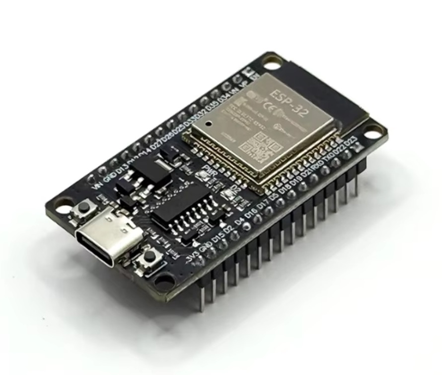
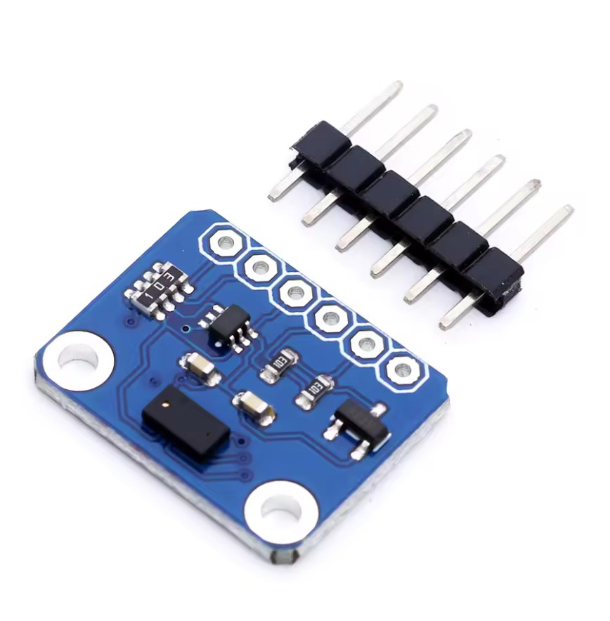
The ESP32 board with CP2102 bridge was chosen for development and flashing convenience, while the VL53L8CH adds more flexibility than simple ranging thanks to the 8×8 multizone sensor and CNH data, useful for future use cases as well.
Bill of materials
Recommended BOM for the reference build.
| Component | Qty | Source | Search / reference | Project notes |
|---|---|---|---|---|
| ESP32 Development Board Type-C CP2102 WiFi | 1 | AliExpress |
ESP32 CP2102 Type-C board
|
Chosen for easy flashing, serial access and practical compatibility on Mac; preferably with headers already soldered. |
| VL53L8CH breakout board + pin strip | 1 | AliExpress |
VL53L8CH module board
|
8×8 multizone ToF sensor; if it does not arrive preassembled it requires pin soldering. |
| 24AWG Dupont jumper wires | 1 kit | AliExpress |
10 cm / 20 cm kit
|
You need enough female-to-female wires to connect the two boards with male headers. |
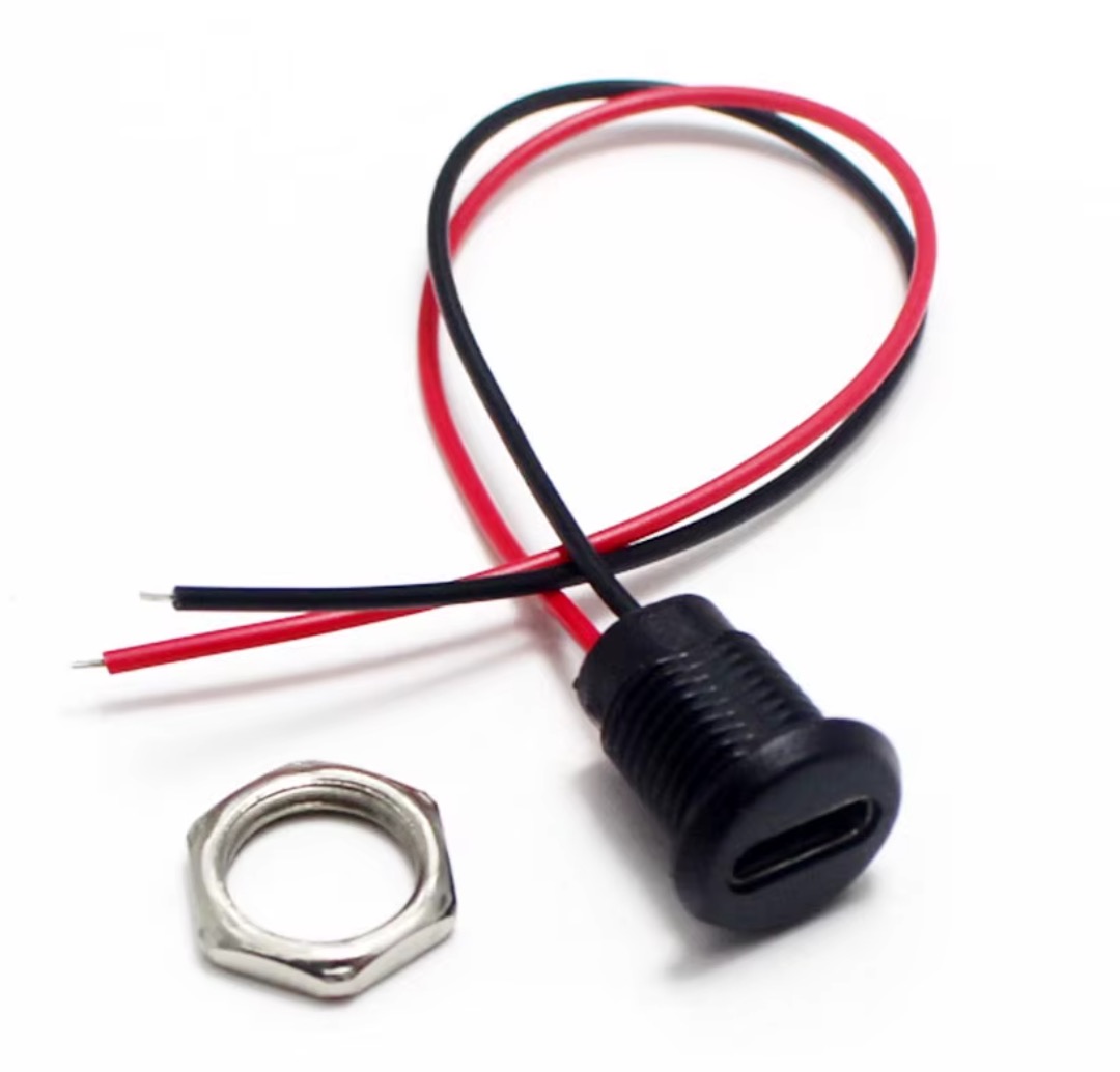
| USB-C panel-mount waterproof connector, 2 wires | 1 | AliExpress |
USB-C waterproof panel mount 2pin
|
Power input for the enclosure. Power only, no USB data. |
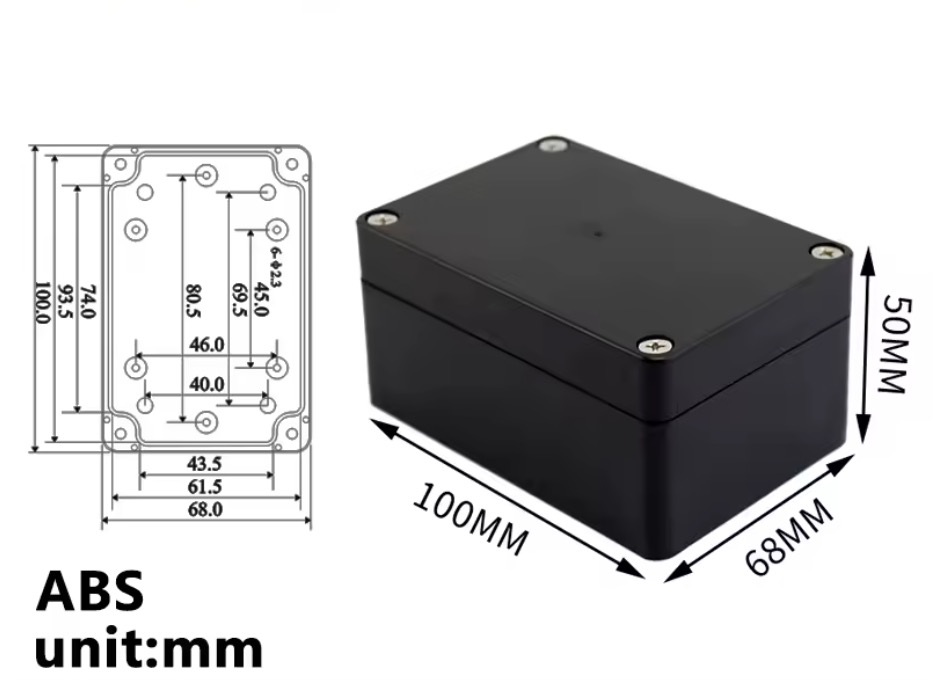
| Waterproof ABS enclosure 100 × 68 × 50 mm | 1 | AliExpress |
ABS waterproof enclosure 100x68x50
|
The size is expressed in millimeters and represents the usable volume of the final case. |
Wiring
Logical connections before closing the enclosure.
| Reference | Use | Implementation note |
|---|---|---|
| ESP32 GPIO 21 → sensor SDA | I²C data | The firmware uses `Wire.begin(21, 22)`. Always verify the pinout of the breakout you purchased. |
| ESP32 GPIO 22 → sensor SCL | I²C clock | Keep wires short and tidy to reduce noise and unstable readings. |
| ESP32 3V3 / proper VIN → sensor power | Power sensor | Some breakouts expose VIN, others 3V3. Do not send 5 V to boards that do not support it. |
| ESP32 GND → sensor GND | Common ground | A clean shared ground is required between sensor, board and power input. |
| USB-C panel red wire → ESP32 5V / VIN | Power enclosure | The 2-wire connector powers the final enclosure and is not used for flashing or USB data. |
| USB-C panel black wire → ESP32 GND | Power enclosure | Program the device from the board native USB before sealing the final case. |
Assembly
Mounting and packaging with the real scene in mind.
The reference build is meant to stay simple to assemble, but final performance depends a lot on how the enclosure is drilled, how the sensor is fixed and how clean the optical opening remains. Practical choices matter more than elegant ones here.
- Program and test the board on the bench before closing the final enclosure.
- If the sensor works behind a window, keep the optical opening clean and not deeply recessed.
- Avoid deep tunnels in front of the sensor, because they unnecessarily narrow the field of view.
- Fix the sensor stably and perpendicular to the passage with spacers, brackets or technical adhesive.
- If the use case is truly outdoor, sealing quality depends on how well the case and connector are drilled and protected.
Firmware
Core functions already included in the reference build.
- persistent on-device configuration for Wi-Fi, threshold, ROI and tracking
- initial access point for provisioning and commissioning
- pairing through setup code and admin token for write operations
- live streaming of the 8×8 matrix through WebSocket
- HTTP API for status, configuration, Wi-Fi provisioning and restart
- blob tracking and line crossing for IN / OUT events
- event upload toward backend or cloud while keeping calibration directly on the sensor
Web utility
Tholus Flow Lite adds a ready-to-use layer on top of the firmware.
Until now the project published the sensor and firmware, but many makers still had to build their own software layer to use the data in practice. Tholus Flow Lite is a small browser utility that connects to the sensor and makes the firmware immediately more usable.
It is intentionally lightweight: a practical dashboard for visualising data, testing the node more easily and starting from something already useful and hackable for small real-world projects.
What it can do
- live entry and exit counts
- estimated current occupancy
- simple live visualisation of doorway activity
- lightweight hourly or daily charts
- basic event history
- simple calibration and tuning controls
How people use it
- build the sensor and flash the firmware
- connect the device to the network or use setup mode
- open the utility in a browser and connect it to the sensor
- view live data and basic analytics
- check history and charts to verify real behaviour on site
- adjust calibration and settings if needed
Usage ideas
Flashing
Firmware installation with Arduino IDE.
Essential toolchain
To make this page genuinely useful, you can download both the published firmware and the official environment used to compile and upload it.
- Install an up-to-date version of Arduino IDE.
- Add the Espressif ESP32 package manager URL in preferences.
- Install the “esp32 by Espressif Systems” package from Boards Manager.
- Select a board compatible with the hardware in use; in most cases “ESP32 Dev Module” is the most practical starting point.
- Install the required libraries: ArduinoJson, arduinoWebSockets (Links2004) and STM32duino VL53L8CH.
- Connect the ESP32 through the board native USB-C port.
- Open the firmware file, verify serial port and board selection, then compile and upload.
- If upload is unstable on Mac, retry with a more conservative upload speed such as 115200.
esp32 by Espressif Systems
Provides the core, WiFi, WebServer, Preferences, ESPmDNS, HTTPClient and upload toolchain.
ArduinoJson
Used for JSON payloads and configuration.
arduinoWebSockets (Links2004)
Handles the live stream over WebSocket.
STM32duino VL53L8CH
Arduino driver for the VL53L8CH ToF sensor.
Commissioning
First boot, pairing and calibration.
- Power the node and check MAC address and node name in serial output; keep setup code and provisioning label at hand.
- Pair the sensor from the app or provisioning tool.
- Set SSID, Wi-Fi password and cloud parameters.
- Wait for the node to appear again on the LAN.
- Open the calibration screen, verify the live matrix and adjust threshold, ROI and counting line in the real installation context.
Checklist
Things not to forget before installation.
- enough female-to-female wires to connect the ESP32 and the sensor breakout
- solder, fine tip and tools for soldering the VL53L8CH headers
- stable 5 V power supply and external USB-C cable
- internal mounting method: spacers, standoffs, technical adhesive or 3D bracket
- optical window or clean cover in front of the sensor, if the enclosure requires it
- external label with serial / MAC / setup code for support and commissioning
References
Essential technical references.
FAQ
Frequent questions for anyone consulting or reusing the project.
Is there anything to keep in mind before using the firmware in the field?
Yes. The published build no longer uses a static AP password: the provisioning password is unique per device and follows the rule `TF-<setup code>`. Serial logs show sensitive values only in masked form.
Why was the VL53L8CH selected?
Because it combines a more controllable FoV than the VL53L7CH with CNH data, which is useful for future scenarios beyond simple people counting: gesture sensing, presence detection and more advanced classifications.
What is the correct assembly flow?
Flash the firmware, test the sensor in open air, complete final wiring, test in the enclosure, then install and calibrate on the real site.